Power Cart
Portable 6-12 Volt DC & 120 Volt AC
|
 |
| |
Table of Contents |
v-24.01.01 - pwrcart1.htm |
|
|


 Introduction
This project started as a simple requirement to have the ability to easily jump-start a 1951 Mercury. This classic vehicle still has the original six (6) volt electrical system. When we are on the road it is very difficult to find something other than twelve (12) volt.
Our first solution was to carry a second six (6) volt battery in the trunk. This became our first line of defense and provided what we needed for emergencies. Also, we quickly learned that we could arrange the second battery in series with the battery in the car and then use a 12 volt to jump start.
However, we still wanted a unit that would temporarily reduce our dependence on access to commercially available electricity and provide power for a few ancillary items such as emergency lighting.
This document will describe how to build a mobile power supply unit using a 12 volt battery source that will provide emergency or temporary backup power for 120 Volts AC and 12 Volts DC. The unit should be easy to transport and easy to maneuver. This project should be a simple, low cost, do it yourself effort.
The following is a list of our requirements for a portable power supply.
|
1.
|
Portable with the ability to expand.
|
|
1.1.
|
Ability to lift unit (without batteries) by one (1) person.
|
|
1.2.
|
Ability to lift unit (with batteries) by two (2) people.
|
|
1.3.
|
Ability to easily transport in the back of a car (Prius).
|
|
1.4.
|
Easy to maneuver (wheels) without lifting.
|
|
2.
|
Ability to Jump start a car with a 6 Volt DC System (800 CCA).
|
|
3.
|
Ability to Jump start a car with a 12 Volt DC System (600 CCA).
|
|
4.
|
Provide two outlets for 120 Volts AC.
|
|
5.
|
Provide one outlet for 12 Volts DC.
|
|
6.
|
Provide a USB charging port.
|
|
7.
|
Ability to open a garage door via the 120 VAC outlet.
|
|
8.
|
Provide emergency lighting via the 120 VAC outlet.
|
|
9.
|
Provide backup power for laptop/mobile phone via 120 VAC outlet.
|
|
10.
|
Provide emergency backup power for LED TV and Connection box.
|
We have made a significant effort to ensure the documents and software technologies are correct and accurate. We reserve the right to make changes without notice at any time. The function delivered in this version is based upon the enhancement requests from a specific group of users. The intent is to provide changes as the need arises and in a timeframe that is dependent upon the availability of resources.
Copyright © 1987-2025
SimoTime Technologies and Services
All Rights Reserved
Tackle the Challenges
Before we built our Mobile Power System we had a 12 volt and a six volt battery sitting on top of a furniture dolly (four pieces of wood bolted together on top of four swivel casters) and it had the advantage of being small and working well on a smooth surface. If we needed to move the batteries outside the garage we either carried them or a hand truck made it easy to lift and maneuver the batteries on unpaved terrain. For a working surface we made numerous trips to the workbench inside the garage or set-up a portable table.
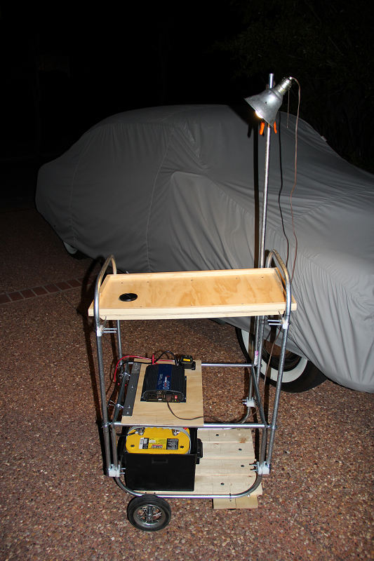
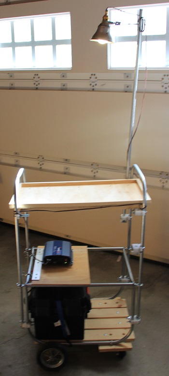
For our mobile power system we wanted all the advantages. The unit needed to be light-weight, easy to transport and maneuver, have its own power source and a small work surface with lighting. A shaded work surface would be nice on a sunny day.
A picture of a prototype power system providing its own lighting. The bulb in the trouble light is a 9.5 watt, 800 lumens LED.
Note: The obvious advantage of using an LED bulb is the power savings. When the cart is functioning without external power the batteries will provide lighting for a longer period of time. A second advantage is the reflector shield stays cool to the touch. A third advantage is durability, we dropped the trouble light and the LED continued to work.
Jumper Cables & 6V Battery
Having a second 6-volt battery (not connected to the primary car battery) in the trunk keeps the item close to the point of usage. The 6-volt battery weighs 36 pounds and by itself is cumbersome to grip and carry to the front of the car.
Placing the battery in a battery box has a number of advantages. The battery box has handles and this makes it easier to lift and carry. The box has a cover that keeps the battery clean and protects the terminals from accidental shorting.
Mobile Power System
The Mobile Power System consists of a Base Component and three attachments. The Base Component is the foundation for the system and may be used by itself to provide temporary electrical power for 12VDC and 120VAC.
The attachments may be added for convenience or to address additional requirements. The attachments need to be added to the power system in a pre-defined order. First, the "Hand-Truck" attachment must be installed. Next, the "Work-Surface" attachment is dependent on the vertical components of the "Hand-Truck" attachment. Last, the "Lighting" attachment is dependent on the vertical components of the "Work-Surface" attachment.
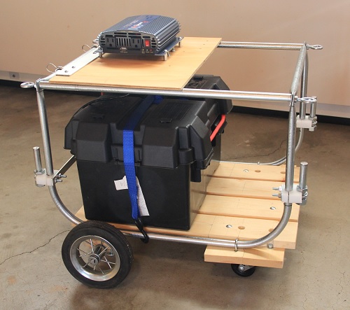
The Base Component
This is the primary component of the mobile power system. It has a metal frame with a wooden base. It has two wheels on a fixed axle and two swivel casters. Two twelve (12) Volt batteries are placed in battery boxes and positioned over the fixed-axle. It has an electrical panel that distributes the 12 VDC and provides the 120 VAC with two standard outlets contained in the inverter unit.
The base unit is 24"W x 28"L x 22"H. Without the batteries it can be easily lifted by one person. A single battery weighs 43 pounds. The total weight of the base unit with two batteries is slightly over 100 pounds.
12 Volt Batteries
We use two (2) OPTIMA® Batteries 8012-021 D34 YELLOWTOP® Starting & Deep-Cycle Battery. Each battery weighs 43 lbs.
|
1.1.
|
Cold Cranking Amps: 750
|
|
1.3.
|
Nominal Voltage: 12 volts
|
|
1.4.
|
Open Circuit Voltage (fully charged): 13.1 volts
|
|
1.5.
|
Internal Resistance (fully charged): 0.0028 ohms
|
|
1.6.
|
Capacity: 55 Ah (C/20)
|
|
1.7.
|
Reserve Capacity: BCI: 120 minutes (25 amp discharge, 80°F (26.7°C), to 10.5 volts cut-off)
|
|
2.
|
Physical Characteristics
|
|
2.1.
|
Plate Design: High purity lead-tin alloy. Wound cell configuration utilizing proprietary
SPIRALCELL TECHNOLOGY®.
|
|
2.2.
|
Electrolyte: Sulfuric acid, H2SO4
|
|
2.4.
|
Case Color: Light Gray
|
|
2.5.
|
Cover Color: "OPTIMA" Yellow
|
Electrical Panel
The electrical panel is a 12 x 18 x .25 inch piece of polypropylene plastic. It contains the electrical components such as the 100-Amp DC Circuit Breaker and DC-to-AC Inverter.
DC Circuit Breaker, 100-Amp
The 100 Amp DC Circuit Breaker is a basic requirement to provide the minimum level of protection. This should not be treated as an optional safety feature.
DC to AC Inverter
An 800 Watt Samlux Inverter is used to provide the 120 VAC.
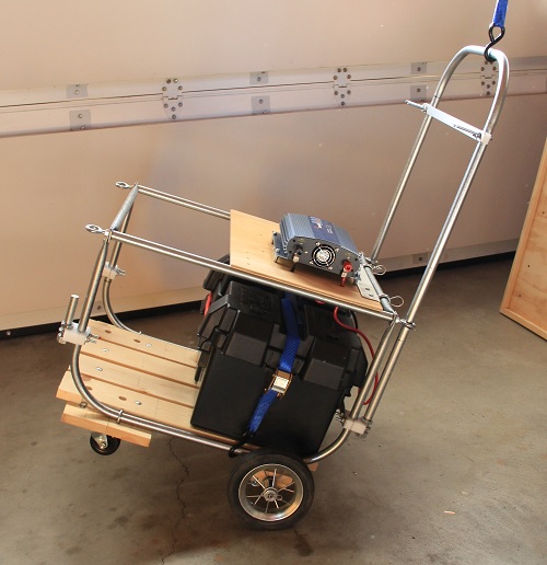
Hand Truck Attachment
The primary purpose for the "Hand Truck Attachment" is to allow the power unit to be tilted and easily maneuvered on two wheels. This is quite convenient when working in tight spaces or moving the unit across uneven terrain.
The secondary purpose for the "Hand Truck Attachment" is to provide two (2) of the four (4) legs needed when adding the "Work Surface Attachment".
The hand truck attachment increases the height of the power cart to 42". The unit may now be tilted and maneuvered on the two larger wheels.
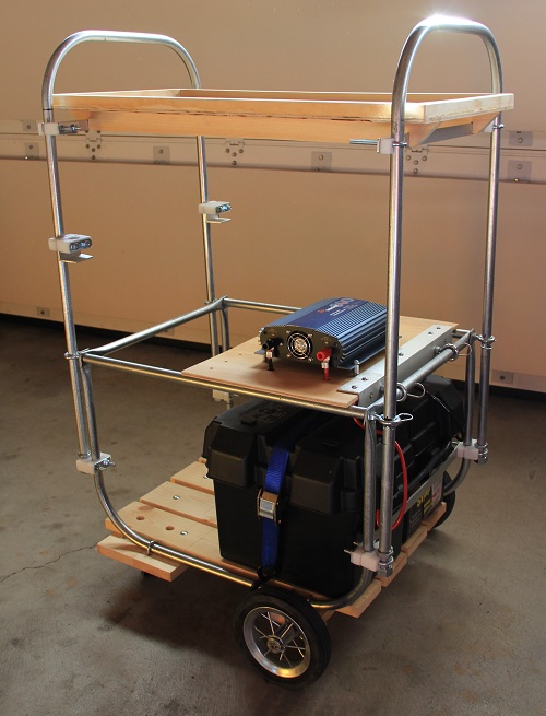
Work Surface Attachment
This attachment provides a 15" x 28" horizontal work surface with a 3/4" high railing to prevents parts and tools from rolling off.
The attachment has two components (or pieces). The first component is the vertical support. The second component is the rectangular work surface.
The work surface attachment contains two pieces, the vertical support piece and the work surface piece. The work surface is 36" above the ground.
Lighting Attachment
This attachment is a four foot pole (a piece of 1/2" electrical conduit) that slips into a bracket on the vertical support for the Work Surface Attachment. The trouble light that contains an LED bulb then clips to the top of the pole. The following shows the reduction in power usage when switching to the LED bulb.
| Lumens | LED | Incandescent | Life Span LED/Incandescent |
| 500 | 7-8 Watts | 40 Watts | 35,000 hours/1200 hours |
| 800 | 9-10 Watts | 60 Watts | 35,000 hours/1200 hours |
| 1600 | 18 Watts | 100 Watts | 25,000 hours/1100 hours |
The lighting attachment is a simple trouble light clipped to a piece of electrical conduit that is inserted into the brackets on the vertical support structure for the work surface attachment. The length of the conduit we use is 48". This brings the total height of the unit to 72" or six feet.
Note: The trouble light originally had a 60 watt incandescent light bulb. To save on power consumption we changed it to an LED light that produced 500 lumens and only consumed 7.5 watts. A secondary benefit of this change was the reduction in heat produced by the LED bulb. Coming into contact with the reflector shield is no longer a painful experience. A third advantage is durability, we dropped the trouble light and the LED continued to work. We keep two spare LED bulbs (1600 and 800 lumens) as backup/replacement bulbs. This gives us the flexibility of switching the bulbs if the primary bulb fails or if we simply want a little more light or a little less power usage.
Electrical Diagram
The following illustration shows the connection of the electrical components for the Power Cart.
| |
|
|
|
|
|
|
|
|
|
|
|
|
Emergency for Overhead Garage Door Opener |
|
|
|
|
|
|
|
|
|
|
|
|
|
Small Unit for Inflating Tires |
|
|
|
|
|
|
|
|
|
|
|
|
|
Trouble Light |
|
|
|
|
|
|
|
|
|
|
|
|
|
|
|
External 120-VAC Devices |
|
|
|
Power Cart Components |
|
|
|
|
|
|
|
|
|
|
|
|
|
|
|
| |
|
|
|
|
|
|
|
|
|
|
|
|
|
Inverter with Circuit Breaker,
refer to Note-1 |
|
|
|
|
|
|
|
|
|
|
|
|
|
|
|
12-Volt Battery,
refer to Note-2 |
|
|
|
|
|
|
|
|
|
|
|
|
|
|
|
12-Volt Battery,
refer to Note-2 |
|
|
|
|
|
|
|
|
|
|
|
|
|
|
|
|
Power Cart Components |
|
|
|
External Devices |
|
|
|
|
|
|
|
|
|
|
|
|
|
|
|
|
External 6-Volt Batteries,
refer to Note-3 |
| |
|
|
|
|
|
|
|
|
Note-1:
Converter for 12-Volt DC to 120 VAC and 100 amp DC Circuit Breaker
|
|
Note-2:
12-Volt Batteries wired in parallel
|
|
Note-3:
The 6-Volt Batteries are not part of the Power Cart
|
|
Wiring Diagram for the Auxiliary Power Supply
|
The preceding wiring diagram shows the 12-Volt batteries connected in a parallel arrangement to increase storage capacity and maintain a 12-Volt connection to the Inverter.
The 6-Volt batteries are not part of the Power Cart. They are shown here as "External Devices". They are actually located in a 1951 Mercury and this connection arrangement is used to jump-start the car from a 12-Volt source.
The 120 VAC from the inverter is used to power a trouble light. It has been used to power a small compressor to inflate tires and to open/close the garage door during a power failure.
Sub-Assemblies
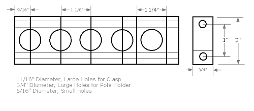
Most of the parts were purchased at a local hardware or auto supply store. However, we did manufacture a few of the parts from polypropylene plastic. The frame for the power unit is made from 1/2" metal electrical conduit. When it was necessary to connect two pieces of conduit we used the manufactured plastic clasps in combination with a purchased U-bracket.
The following illustration shows the template used to construct the polypropylene plastic clasps.
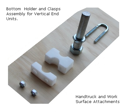
The following shows the sub-assembly that is used as the bottom holder for the vertical-end units of the hand truck and work-surface attachments.
Bill of Materials
The following of a list of the materials required to build the Mobile Power System.
| Quantity | Unit | Description |
|---|
| 4 | 8-ft | 1/2" Electrical Conduit (Metal, 8-ft length) |
| 16 | each | U-Bolt, 1/4" x 3/4" x 2 3/4" |
| 4 | each | Eye-Bolt, 1/4" x 3/4" x 2 3/4" |
| 6 | each | .093 x 2" Hitch Pin |
| 2 | each | Wheels. 7" diameter |
| 2 | each | Casters (swivel), 3" diameter wheels |
| 1 | 3-ft | 3/8" diameter steel rod (for back axle) |
| 2 | 8-ft | 1" x 5" Pine or Douglas Fir (8-ft length |
| 1 | 8-ft | 1" x 1" Pine or Douglas Fir (8-ft length |
| 1 | 6-ft | 1" x 2" Pine or Douglas Fir (6-ft length |
| 4 | each | 1.125" x 2" x .75" double-sided Polypropylene Plastic Clasp |
| 12 | each | .5625" x 2" x .75" single-sided Polypropylene Plastic Clasp |
| 4 | each | 1.125" x 2" x .75" Polypropylene Plastic Holder |
Tools & Equipment
The following is a list of the tools and equipment that we keep with the mobile power unit.
|
1.
|
Thirty (30) foot extension cord
|
|
2.
|
Three foot extension cord with three outlets
|
|
4.
|
Clip-on Trouble light with LED-bulb 7-Watt, 500 Lumens
|
|
5.
|
Extra LED-bulb 10-Watt, 800 Lumens
|
|
6.
|
Extra LED-bulb 18-Watt, 1600 Lumens
|
|
8.2.
|
Flat Blade Screw Driver
|
|
8.3.
|
Phillips Screw Driver
|
|
8.6.
|
Wrench Set (box and Open End)
|
In addition to the tools in the preceding list the following is a list of the tools and equipment that we used to build the mobile power unit.
|
2.
|
Adjustable Carpenter's Square
|
|
3.
|
Bending tool for 1/2" electrical conduit
|
|
8.
|
Powered Bench Saw or Miter Saw
|
|
10.1.
|
7/64" Drill Bit (twist for metal or plastic)
|
|
10.2.
|
5/16" Drill Bit (twist for wood, metal or plastic)
|
|
10.3.
|
5/8" Drill Bit (flat for wood or plastic)
|
|
10.4.
|
11/16" Drill Bit (flat for wood or plastic)
|
|
10.5.
|
3/4" Drill Bit (flat for wood or plastic)
|
Vendors & Suppliers
The following is a lists of Vendors and suppliers.
|
1.
|
Napa Auto Parts
7426 Redwood Blvd,
Novato, CA 94945
(415) 897-1188
|
|
2.
|
Pini Hardware
1535 S Novato Blvd,
Novato, CA 94947
(415) 892-1577
|
|
3.
|
BatteriesPlus
2064 4th St,
San Rafael, CA 94901
(415) 455-9221
|
|
4.
|
Industrial Plastic Supply, Inc.
2240 S. Dupont Drive,
Anaheim, CA 92806
http://www.iplasticsupply.com/
|
|
5.
|
Northern Arizona Wind & Sun
4091 E Huntington Drive,
Flagstaff, AZ 86004
http://www.solar-electric.com/
|
Summary
The purpose of this document is to provide the reader with information for building a mobile power unit. This document and the links to other documents are intended to provide a choice of alternatives.
In the world of programming there are many ways to solve a problem. This documentation and software were developed and tested on systems that are configured for a SIMOTIME environment based on the hardware, operating systems, user requirements and security requirements. Therefore, adjustments may be needed to execute the jobs and programs when transferred to a system of a different architecture or configuration.
SIMOTIME Services has experience in moving or sharing data or application processing across a variety of systems. For additional information about SIMOTIME Services or Technologies please contact us using the information in the Contact or Feedback section of this document.
Software Agreement and Disclaimer
Permission to use, copy, modify and distribute this software, documentation or training material for any purpose requires a fee to be paid to SimoTime Technologies. Once the fee is received by SimoTime the latest version of the software, documentation or training material will be delivered and a license will be granted for use within an enterprise, provided the SimoTime copyright notice appear on all copies of the software. The SimoTime name or Logo may not be used in any advertising or publicity pertaining to the use of the software without the written permission of SimoTime Technologies.
SimoTime Technologies makes no warranty or representations about the suitability of the software, documentation or learning material for any purpose. It is provided "AS IS" without any expressed or implied warranty, including the implied warranties of merchantability, fitness for a particular purpose and non-infringement. SimoTime Technologies shall not be liable for any direct, indirect, special or consequential damages resulting from the loss of use, data or projects, whether in an action of contract or tort, arising out of or in connection with the use or performance of this software, documentation or training material.
Downloads and Links
This section includes links to documents with additional information that are beyond the scope and purpose of this document. The first group of documents may be available from a local system or via an internet connection, the second group of documents will require an internet connection.
Note: A SimoTime License is required for the items to be made available on a local system or server.
Current Server or Internet Access
The following links may be to the current server or to the Internet.
Note: The latest versions of the SimoTime Documents and Program Suites are available on the Internet and may be accessed using the  icon. If a user has a SimoTime Enterprise License the Documents and Program Suites may be available on a local server and accessed using the
  icon.
icon.
Read about a classic 1951 Mercury and enjoy a few pictures. SimoTime is a proud supporter of the preservation of legacy or classics automobiles. This is an excellent example of the styling and engineering of the 1950's. Here's to the "Lead-Sled" and "Flatheads Forever".
Internet Access Required
The following links will require an internet connection.
A good place to start is
The SimoTime Home Page
for access to white papers, program examples and product information. This link requires an Internet Connection
Glossary of Terms
Explore the Glossary of Terms for a list of terms and definitions used in this suite of documents and white papers.
Contact or Feedback
This document was created and is maintained by SimoTime Technologies. If you have any questions, suggestions, comments or feedback please use the following contact information.
|
1.
|
Send an e-mail to our helpdesk.
|
|
2.
|
Our telephone numbers are as follows.
|
|
2.1.
|
1 415 763-9430 office-helpdesk
|
|
2.2.
|
1 415 827-7045 mobile
|
We appreciate hearing from you.
Company Overview
SimoTime Technologies was founded in 1987 and is a privately owned company. We specialize in the creation and deployment of business applications using new or existing technologies and services. We have a team of individuals that understand the broad range of technologies being used in today's environments. Our customers include small businesses using Internet technologies to corporations using very large mainframe systems.
Quite often, to reach larger markets or provide a higher level of service to existing customers it requires the newer Internet technologies to work in a complementary manner with existing corporate mainframe systems. We specialize in preparing applications and the associated data that are currently residing on a single platform to be distributed across a variety of platforms.
Preparing the application programs will require the transfer of source members that will be compiled and deployed on the target platform. The data will need to be transferred between the systems and may need to be converted and validated at various stages within the process. SimoTime has the technology, services and experience to assist in the application and data management tasks involved with doing business in a multi-system environment.
Whether you want to use the Internet to expand into new market segments or as a delivery vehicle for existing business functions simply give us a call or check the web site at http://www.simotime.com
Copyright © 1987-2025
SimoTime Technologies and Services
All Rights Reserved |
| When technology complements business |
| http://www.simotime.com |